
Page 95 - Modern Control of DC-Based Power Systems
P. 95
Small-Signal Analysis of Cascaded Systems 59
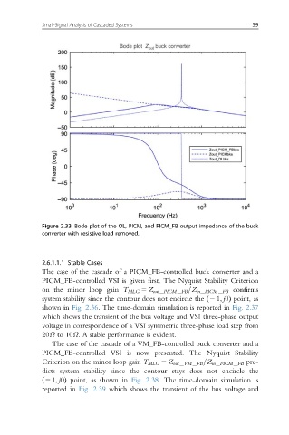
Figure 2.33 Bode plot of the OL, PICM, and PICM_FB output impedance of the buck
converter with resistive load removed.
2.6.1.1.1 Stable Cases
The case of the cascade of a PICM_FB-controlled buck converter and a
PICM_FB-controlled VSI is given first. The Nyquist Stability Criterion
on the minor loop gain T MLG 5 Z out PICM FB =Z in PICM FB confirms
system stability since the contour does not encircle the ð2 1; j0Þ point, as
shown in Fig. 2.36. The time-domain simulation is reported in Fig. 2.37
which shows the transient of the bus voltage and VSI three-phase output
voltage in correspondence of a VSI symmetric three-phase load step from
20Ω to 10Ω. A stable performance is evident.
The case of the cascade of a VM_FB-controlled buck converter and a
PICM_FB-controlled VSI is now presented. The Nyquist Stability
Criterion on the minor loop gain T MLG 5 Z out VM FB =Z in PICM FB pre-
dicts system stability since the contour stays does not encircle the
ð2 1; j0Þ point, as shown in Fig. 2.38. The time-domain simulation is
reported in Fig. 2.39 which shows the transient of the bus voltage and