
Page 94 - Modern Control of DC-Based Power Systems
P. 94
58 Modern Control of DC-Based Power Systems
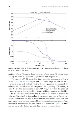
Figure 2.32 Bode plot of the OL, PICM, and PICM_FB output impedance of the buck
converter with resistive load.
addition of the PI current loop and then of the outer PI voltage loop
modify the phase of the output impedance at low frequencies.
The case of VM_FB-controlled buck converter produces a different
result. Figs. 2.34 and 2.35 depict how the output impedance of the buck
converter with and without resistive load, respectively, is modified by
effect of the control action with respect to the open-loop (OL subscript)
case. Notice that the addition of the PID voltage loop has the effect of
making a negative incremental impedance within the control bandwidth.
In the next two subsections, the stability of the system is assessed by
using the Nyquist Criterion applied to the minor loop gain in frequency-
domain simulations as well as time-domain simulations. Two cases are
analyzed: a stable one and an unstable one, depending on the types of the
controllers implemented for the source buck converter. Table 2.3 sum-
marizes the results that are presented in the next two subsections.