
Page 93 - Modern Control of DC-Based Power Systems
P. 93
Small-Signal Analysis of Cascaded Systems 57
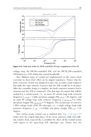
Figure 2.31 Bode plot of the OL, PICM, and PICM_FB input impedances of the VSI.
voltage loop, the PICM-controlled VSI, and the PICM_FB-controlled
VSI behave as a CPL within the control bandwidth.
Two different types of control are implemented on the source buck
converter to show their effect on its output impedance. Notice that the
buck converter control was designed to take into account a load resistance
that sinks the same amount of power that the VSI would do in its place.
After the controller design is complete, the buck converter resistive load is
removed and the VSI is connected. The first type of control that will be
analyzed is a current mode, i.e., an inner PI current loop with crossover
frequency f c_PICM 5 1 kHz and phase margin PM_ PICM 5 80 degrees, and
an outer PI voltage loop with crossover frequency f c_PICM_FB 5 0.1 kHz
and phase margin PM_ PICM_FB 5 70 degrees. The second type of control is
a PID voltage mode (VM_FB subscript), i.e., a single voltage loop with
crossover frequency f c_VM 5 0.5 kHz and phase margin PM_ VM 5 52
degrees.
The current mode control case is analyzed first. Figs. 2.32 and 2.33
depict how the output impedance of the buck converter with and with-
out resistive load, respectively, is modified by effect of the control action
with respect to the open-loop (OL subscript) case. Notice how the