
Page 97 - Modern Control of DC-Based Power Systems
P. 97
Small-Signal Analysis of Cascaded Systems 61
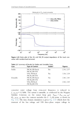
Figure 2.35 Bode plot of the OL and VM_FB output impedance of the buck con-
verter with resistive load removed.
Table 2.3 Summary of Results for Stable and Unstable Cases
Case Type of Control Stable? Figures
Stable PICM_FB Buck Yes 2.36, 2.37
PICM_FB VSI
VM_FB Buck Yes 2.38, 2.39
PICM_FB VSI
Unstable PICM_FB Buck No 2.40, 2.41
PICM_FB VSI
VM_FB Buck No 2.42, 2.43
PICM_FB VSI
converter outer voltage loop cross-over frequency is reduced to
f c_VM_FB 5 0.2 kHz. The system is unstable, as confirmed by the Nyquist
Stability Criterion on the minor loop gain T MLG 5 Z out VM FB =
Z in PICM FB since the contour encircles the ð2 1; j0Þ point, as shown in
Fig. 2.42. The time-domain simulation is given Fig. 2.43 which show the
transient of the bus voltage and VSI three-phase output voltage in