
Page 22 - Modern Optical Engineering The Design of Optical Systems
P. 22
Optics Overview 5
Although most optical materials may be assumed to be isotropic,
with a completely homogeneous index of refraction, there are some
significant exceptions. The earth’s atmosphere at any given elevation is
quite uniform in index, but when considered over a large range of alti-
tudes, the index varies from about 1.0003 at sea level to 1.0 at extreme
altitudes. Therefore, light rays passing through the atmosphere do not
travel in exactly straight lines; they are refracted to curve toward the
earth, i.e., toward the higher index. Gradient index optical glasses are
deliberately fabricated to bend light rays in controlled curved paths. In
this text we shall assume homogeneous media unless specifically stated
otherwise. We also assume that lens elements are immersed in air.
1.3 Snell’s Law of Refraction
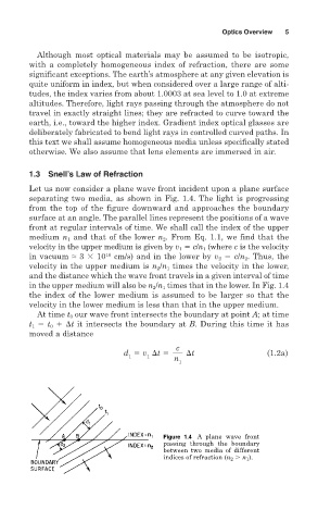
Let us now consider a plane wave front incident upon a plane surface
separating two media, as shown in Fig. 1.4. The light is progressing
from the top of the figure downward and approaches the boundary
surface at an angle. The parallel lines represent the positions of a wave
front at regular intervals of time. We shall call the index of the upper
medium n 1 and that of the lower n 2 . From Eq. 1.1, we find that the
velocity in the upper medium is given by v 1 c/n 1 (where c is the velocity
in vacuum ≈ 3 10 10 cm/s) and in the lower by v 2 c/n 2 . Thus, the
velocity in the upper medium is n 2 /n 1 times the velocity in the lower,
and the distance which the wave front travels in a given interval of time
in the upper medium will also be n 2 /n 1 times that in the lower. In Fig. 1.4
the index of the lower medium is assumed to be larger so that the
velocity in the lower medium is less than that in the upper medium.
At time t 0 our wave front intersects the boundary at point A; at time
t 1 t 0
t it intersects the boundary at B. During this time it has
moved a distance
c
d v
t
t (1.2a)
1 1 n
1
Figure 1.4 A plane wave front
passing through the boundary
between two media of different
indices of refraction (n 2 n 1 ).