
Page 25 - Modern Optical Engineering The Design of Optical Systems
P. 25
8 Chapter One
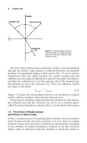
Figure 1.7 Relationship between
a ray incident on a plane surface
and the resultant reflected and
refracted rays.
All of the light incident upon a boundary surface is not transmitted
through the surface; some portion is reflected back into the incident
medium. A construction similar to that used in Fig. 1.5 can be used to
demonstrate that the angle between the surface normal and the
reflected ray (the angle of reflection) is equal to the angle of incidence,
and that the reflected ray is on the opposite side of the normal from
the incident ray (as is the refracted ray). Thus, for reflection, Snell’s
law takes on the form
I I (1.4)
incident reflected
Figure 1.7 shows the relationship between a ray incident on a plane
surface and the resultant reflected and refracted rays.
At this point it should be emphasized that the incident ray, the normal,
the reflected ray, and the refracted ray all lie in a common plane,
called the plane of incidence, which in Fig. 1.7 is the plane of the paper.
1.4 The Action of Simple Lenses
and Prisms on Wave Fronts
In Fig. 1.8 a point source P is emitting light; as before, the arcs centered
about P represent the successive positions of a wave front at regular
intervals of time. The wave front is incident on a biconvex lens consisting
of two surfaces of rotation bounding a medium of (in this instance)
higher index of refraction than the medium in which the source is