
Page 29 - Modern Optical Engineering The Design of Optical Systems
P. 29
12 Chapter One
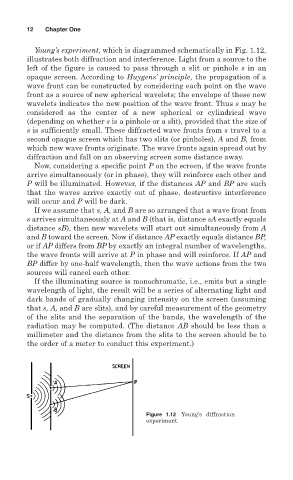
Young’s experiment, which is diagrammed schematically in Fig. 1.12,
illustrates both diffraction and interference. Light from a source to the
left of the figure is caused to pass through a slit or pinhole s in an
opaque screen. According to Huygens’ principle, the propagation of a
wave front can be constructed by considering each point on the wave
front as a source of new spherical wavelets; the envelope of these new
wavelets indicates the new position of the wave front. Thus s may be
considered as the center of a new spherical or cylindrical wave
(depending on whether s is a pinhole or a slit), provided that the size of
s is sufficiently small. These diffracted wave fronts from s travel to a
second opaque screen which has two slits (or pinholes), A and B, from
which new wave fronts originate. The wave fronts again spread out by
diffraction and fall on an observing screen some distance away.
Now, considering a specific point P on the screen, if the wave fronts
arrive simultaneously (or in phase), they will reinforce each other and
P will be illuminated. However, if the distances AP and BP are such
that the waves arrive exactly out of phase, destructive interference
will occur and P will be dark.
If we assume that s, A, and B are so arranged that a wave front from
s arrives simultaneously at A and B (that is, distance sA exactly equals
distance sB), then new wavelets will start out simultaneously from A
and B toward the screen. Now if distance AP exactly equals distance BP,
or if AP differs from BP by exactly an integral number of wavelengths,
the wave fronts will arrive at P in phase and will reinforce. If AP and
BP differ by one-half wavelength, then the wave actions from the two
sources will cancel each other.
If the illuminating source is monochromatic, i.e., emits but a single
wavelength of light, the result will be a series of alternating light and
dark bands of gradually changing intensity on the screen (assuming
that s, A, and B are slits), and by careful measurement of the geometry
of the slits and the separation of the bands, the wavelength of the
radiation may be computed. (The distance AB should be less than a
millimeter and the distance from the slits to the screen should be to
the order of a meter to conduct this experiment.)
Figure 1.12 Young’s diffraction
experiment.