
Page 33 - Modern Optical Engineering The Design of Optical Systems
P. 33
16 Chapter One
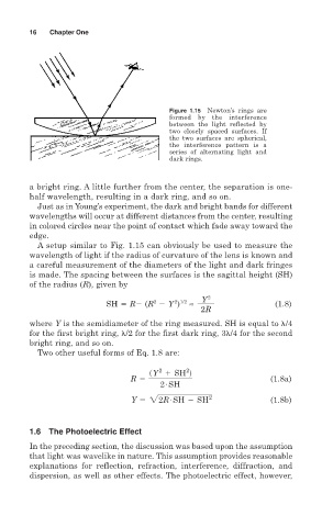
Figure 1.15 Newton’s rings are
formed by the interference
between the light reflected by
two closely spaced surfaces. If
the two surfaces are spherical,
the interference pattern is a
series of alternating light and
dark rings.
a bright ring. A little further from the center, the separation is one-
half wavelength, resulting in a dark ring, and so on.
Just as in Young’s experiment, the dark and bright bands for different
wavelengths will occur at different distances from the center, resulting
in colored circles near the point of contact which fade away toward the
edge.
A setup similar to Fig. 1.15 can obviously be used to measure the
wavelength of light if the radius of curvature of the lens is known and
a careful measurement of the diameters of the light and dark fringes
is made. The spacing between the surfaces is the sagittal height (SH)
of the radius (R), given by
Y 2
2 1/2
2
SH R (R Y ) ≈ (1.8)
2R
where Y is the semidiameter of the ring measured. SH is equal to /4
for the first bright ring, /2 for the first dark ring, 3 /4 for the second
bright ring, and so on.
Two other useful forms of Eq. 1.8 are:
2
2
sY 1 SH d
R 5 # (1.8a)
2 SH
#
Y 5 22R SH 2 SH 2 (1.8b)
1.6 The Photoelectric Effect
In the preceding section, the discussion was based upon the assumption
that light was wavelike in nature. This assumption provides reasonable
explanations for reflection, refraction, interference, diffraction, and
dispersion, as well as other effects. The photoelectric effect, however,