
Page 32 - Modern Optical Engineering The Design of Optical Systems
P. 32
Optics Overview 15
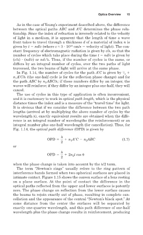
As in the case of Young’s experiment described above, the difference
between the optical paths ABC and A′C determines the phase rela-
tionship. Since the index of refraction is inversely related to the velocity
of light in a medium, it is apparent that the length of time a wave
front takes to travel through a thickness d of a material of index n is
10
given by t nd/c (where c ≈ 3 10 cm/s velocity of light). The con-
stant frequency of electromagnetic radiation is given by c/ , so that the
number of cycles which take place during the time t nd/c is given by
(c/ ) (nd/c) or nd/ . Thus, if the number of cycles is the same, or
differs by an integral number of cycles, over the two paths of light
traversed, the two beams of light will arrive at the same phase.
1
In Fig. 1.14, the number of cycles for the path A′C is given by
2
n 1 A′C/ (the one-half cycle is for the reflection phase change) and for
the path ABC by n 2 ABC/ ; if these numbers differ by an integer, the
waves will reinforce; if they differ by an integer plus one-half, they will
cancel.
The use of cycles in this type of application is often inconvenient,
and it is customary to work in optical path length, which is the physical
distance times the index and is a measure of the “travel time” for light.
It is obvious that if we consider the difference between the two path
lengths (arrived at by multiplying the above number of cycles by the
wavelength ), exactly equivalent results are obtained when the diffe-
rence is an integral number of wavelengths (for reinforcement) or an
integral number plus one-half wavelength (for cancellation). Thus, for
Fig. 1.14, the optical path difference (OPD) is given by
l
OPD 5 1 n A9C 2 n ABC (1.7)
2
1
2
or
l
OPD 5 1 2n t cos
2
2
when the phase change is taken into account by the /2 term.
The term “Newton’s rings” usually refers to the ring pattern of
interference bands formed when two spherical surfaces are placed in
intimate contact. Figure 1.15 shows the convex surface of a lens resting
on a plane surface. At the point of contact the difference in the
optical paths reflected from the upper and lower surfaces is patently
zero. The phase change on reflection from the lower surface causes
the beams to rejoin exactly out of phase, resulting in complete can-
cellation and the appearance of the central “Newton’s black spot.” At
some distance from the center the surfaces will be separated by
exactly one-quarter wavelength, and this path difference of one-half
wavelength plus the phase change results in reinforcement, producing