
Page 27 - Modern Optical Engineering The Design of Optical Systems
P. 27
10 Chapter One
Figure 1.9 The passage of a
wave front through a diverging,
or negative, lens element.
expect to find a concentration of light; all that would be observed would
be the general illumination produced by the light emanating from P.
This type of image is called a virtual image to distinguish it from the
type of image diagramed in Fig. 1.8, which is called a real image. Thus
a virtual image may be observed directly or may serve as a source to be
reimaged by a subsequent lens system, but it cannot be produced on a
screen. The terms “real” and “virtual” also may be applied to rays,
where “virtual” applies to the extended part of a real ray.
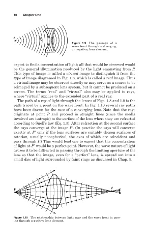
The path of a ray of light through the lenses of Figs. 1.8 and 1.9 is the
path traced by a point on the wave front. In Fig. 1.10 several ray paths
have been drawn for the case of a converging lens. Note that the rays
originate at point P and proceed in straight lines (since the media
involved are isotropic) to the surface of the lens where they are refracted
according to Snell’s law (Eq. 1.3). After refraction at the second surface
the rays converge at the image P′. (In practice the rays will converge
exactly at P′ only if the lens surfaces are suitably chosen surfaces of
rotation, usually nonspherical, the axes of which are coincident and
pass through P.) This would lead one to expect that the concentration
of light at P′ would be a perfect point. However, the wave nature of light
causes it to be diffracted in passing through the limiting aperture of the
lens so that the image, even for a “perfect” lens, is spread out into a
small disc of light surrounded by faint rings as discussed in Chap. 9.
Figure 1.10 The relationship between light rays and the wave front in pass-
ing through a positive lens element.