
Page 31 - Modern Optical Engineering The Design of Optical Systems
P. 31
14 Chapter One
blue light which will occur at a point where the other wavelengths are
still illuminating the screen. Similarly, the dark band for red light will
occur where blue and other wavelengths are illuminating the screen.
Thus a series of colored bands is produced, starting with white on the
axis and progressing through red, blue, green, orange, red, violet, green,
and violet, as the path difference increases. Further from the axis,
however, the various light and dark bands from all the visible wave-
lengths become so “scrambled” that the band structures blend together
and disappear.
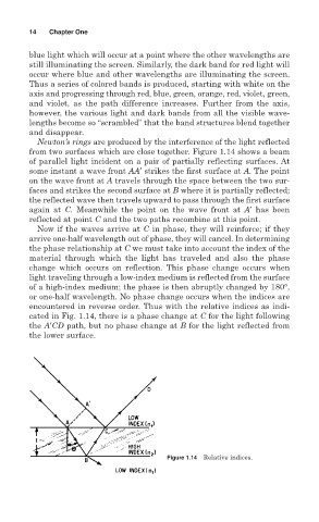
Newton’s rings are produced by the interference of the light reflected
from two surfaces which are close together. Figure 1.14 shows a beam
of parallel light incident on a pair of partially reflecting surfaces. At
some instant a wave front AA′ strikes the first surface at A. The point
on the wave front at A travels through the space between the two sur-
faces and strikes the second surface at B where it is partially reflected;
the reflected wave then travels upward to pass through the first surface
again at C. Meanwhile the point on the wave front at A′ has been
reflected at point C and the two paths recombine at this point.
Now if the waves arrive at C in phase, they will reinforce; if they
arrive one-half wavelength out of phase, they will cancel. In determining
the phase relationship at C we must take into account the index of the
material through which the light has traveled and also the phase
change which occurs on reflection. This phase change occurs when
light traveling through a low-index medium is reflected from the surface
of a high-index medium; the phase is then abruptly changed by 180°,
or one-half wavelength. No phase change occurs when the indices are
encountered in reverse order. Thus with the relative indices as indi-
cated in Fig. 1.14, there is a phase change at C for the light following
the A′CD path, but no phase change at B for the light reflected from
the lower surface.
Figure 1.14 Relative indices.