
Page 23 - Modern Optical Engineering The Design of Optical Systems
P. 23
6 Chapter One
in the upper medium, and a distance
c
d v
t
t (1.2b)
2 2
n
2
in the lower medium.
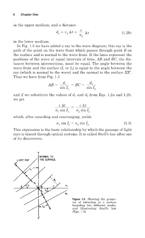
In Fig. 1.5 we have added a ray to the wave diagram; this ray is the
path of the point on the wave front which passes through point B on
the surface and is normal to the wave front. If the lines represent the
positions of the wave at equal intervals of time, AB and BC, the dis-
tances between intersections, must be equal. The angle between the
wave front and the surface (I 1 or I 2 ) is equal to the angle between the
ray (which is normal to the wave) and the normal to the surface XX′.
Thus we have from Fig. 1.5
d
1
d 2
AB BC
sin I sin I
1 2
and if we substitute the values of d 1 and d 2 from Eqs. 1.2a and 1.2b,
we get
c
t c
t
n sin I n sin I
1 1 2 2
which, after canceling and rearranging, yields
n sin I n sin I (1.3)
1 1 2 2
This expression is the basic relationship by which the passage of light
rays is traced through optical systems. It is called Snell’s law after one
of its discoverers.
Figure 1.5 Showing the geome-
try of refraction at a surface
bounding two different media,
and illustrating Snell’s law
(Eqn. 1.3).