
Page 58 - Modern Optical Engineering The Design of Optical Systems
P. 58
Paraxial Optics and Calculations 41
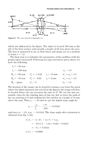
Figure 3.4 The rays traced in Example 3.1.
which are indicated in the figure. The object is located 300 mm to the
left of the first surface and extends a height of 20 mm above the axis.
The lens is immersed in air, so that object and image are in a medium
of index n 1.0.
The first step is to tabulate the parameters of the problem with the
proper signs associated. Following the sign convention given above, we
have the following:
h 20 mm
l 300 mm n 1.0
1 1
R 50 mm C 0.02 t 10 mm n′ n 1.5
1 1 1 1 2
R 50 mm C 0.02 t 2 mm n′ n 1.6
2 2 2 2 3
R plano C 0 n′ 1.0
3 3 3
The location of the image can be found by tracing a ray from the point
where the object intersects the axis (O in the figure); the image will then
be located where the ray recrosses the axis at O′. We can use any rea-
sonable value for the starting data of this ray. Let us trace the path of
the ray starting at O and striking the first surface at a height of 10 mm
above the axis. Thus y 1 10 and we get the initial slope angle by
10
y 1
u 0.0333
1
l 300
1
and since n 1 1.0, n 1 u 1 0.0333. The slope angle after refraction is
obtained from Eq. 3.16a.
n′ u′ y (n′ n ) C n u
1 1 1 1 1 1 1 1
10 (1.5 1.0) ( 0.02) 0.0333
0.1 0.0333
n′ u′ 0.0666
1 1