
Page 109 - Modular design for machine tools
P. 109
Engineering Guides and Future Perspectives of Modular Design 73
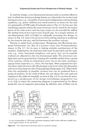
In modular design, a two-dimensional decision table is another effective
tool, in which two dominant design factors are allocated to the vertical and
horizontal axes, e.g., versatility of structural configuration and machining
capability, e.g., power, stiffness and metal removal, as shown for the case
of a planomiller of TOS make (Czechoslovakia) in Fig. 2-5. In this case, the
machining capacity within the same structure can be varied by the output
power of the main motor; also the type variety can be extended by adding
the milling head of ram type to that of quill type. As a simple method, an
one-dimensional table is helpful in rationally managing the design, as
shown in Fig. 2-6, where the structure of the milling machine is reinforced
by the overarm and stay, and furthermore the auxiliary column.
Having in mind these predecessors, Brankamp and Herrmann pro-
posed furthermore the idea of a function chain (das Funktionskette),
shown in Fig. 2-7, for its ease in finding suitable combinations of the
modules. Importantly, the functions that must be provided and the mod-
ules, e.g., units, functional complexes, and parts, that can be possibly
realized are allocated in the two-dimensional table. The structural con-
figuration can be generated by choosing the suitable module from a group
of the modules, which are allocated in every line in the table, showing a
zigzag choice trajectory, i.e., chain. On this topic, Dietz proposed two sim-
ilar ideas called structure (der Baukasten)-structural entity (die Baureihe)
and connecting diagram (das Verknupfungs- Diagramm) [11]. These facil-
itate the estimation of possible variants that can be produced from a
group of modules. In the work of Dietz, the row shows the unit and unit
complex in the order of assembly, as seen in Fig. 2-8. It can thus be inter-
preted as a predecessor of the design methodology proposed by Lee
et al. [12], in which the connecting diagram is represented by the direct
graph for ease of computer processing. In addition, that of Dietz can be
Increased strength
Increased versatility
In case of planomiller of TOS make (maximum clamping width of table 1600 mm; spindle drive
power approximately 10, 20, and 40 HP).
Figure 2-5 Two- dimensional decision table for modular design.