
Page 113 - Modular design for machine tools
P. 113
76 Modular Design Guide and Machine Tools Description
Structural entities
1
Driving
1
2 power P (kW) P 1 P 2 P 3
Units 2 Transmission Type I Type II
3 box i = 1:3.15
4
3 Headstock Size 1 Size 2 Size 3
5
7
Spindle
4 D D D D D D
6 (chuck dia. mm) 1 2 3 4 5 6
7 8 Cross slide
5 (Traveling l x1 l x2 l x3
length x mm)
9 Carriage
6 (Traveling l z1 l z2
length z mm)
Feed motor
7
(driving force kN) F 1 F 2
8 Base Size I Size II
9 Cover panel Machine (a modular system)
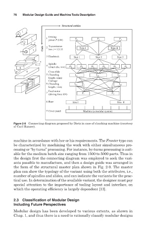
Figure 2-8 Connecting diagram proposed by Dietz in case of chucking machine (courtesy
of Carl Hanser).
machine in accordance with her or his requirements. The Fronter type can
be characterized by machining the work with either simultaneous pro-
cessing or “by turns” processing. For instance, by-turns processing is suit-
able for the medium batch size ranging from 1500 to 5000 parts. Thus in
the design first the connecting diagram was employed to seek the vari-
ants possible to manufacture, and then a design guide was arranged in
the form of the structural master plan shown in Fig. 2-9. The master
plan can show the typology of the variant using both the attributes, i.e.,
number of spindles and slides, and can indicate the variants for the prac-
tical use. In determination of the available variant, the designer must pay
special attention to the importance of tooling layout and interface, on
which the operating efficiency is largely dependent [13].
2.3 Classification of Modular Design
Including Future Perspectives
Modular design has been developed to various extents, as shown in
Chap. 1, and thus there is a need to rationally classify modular designs