
Page 144 - Modular design for machine tools
P. 144
104 Modular Design Guide and Machine Tools Description
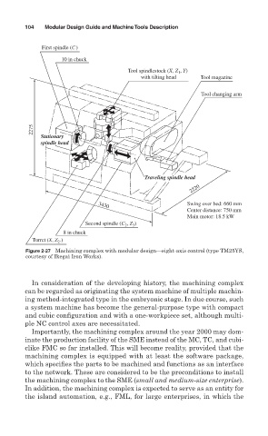
First spindle (C)
10 in chuck
, Y)
Tool spindlestock (X, Z 1
with tilting head Tool magazine
Tool changing arm
2275
Stationary
spindle head
Traveling spindle head
2220
Swing over bed: 660 mm
3430
Center distance: 750 mm
Main motor: 18.5 kW
Second spindle (C , Z )
3
2
8 in chuck
Turret (X, Z .)
2
Figure 2-27 Machining complex with modular design— eight-axis control (type TM25YS,
courtesy of Ikegai Iron Works).
In consideration of the developing history, the machining complex
can be regarded as originating the system machine of multiple machin-
ing method-integrated type in the embryonic stage. In due course, such
a system machine has become the general-purpose type with compact
and cubic configuration and with a one-workpiece set, although multi-
ple NC control axes are necessitated.
Importantly, the machining complex around the year 2000 may dom-
inate the production facility of the SME instead of the MC, TC, and cubi-
clike FMC so far installed. This will become reality, provided that the
machining complex is equipped with at least the software package,
which specifies the parts to be machined and functions as an interface
to the network. These are considered to be the preconditions to install
the machining complex to the SME (small and medium-size enterprise).
In addition, the machining complex is expected to serve as an entity for
the island automation, e.g., FML, for large enterprises, in which the