
Page 193 - Modular design for machine tools
P. 193
Application of Machine Tool Description to Engineering Design 153
X Y 1 2 3 4 5 6 7 8 9 10 1 2 3 4 5 6 7 8 9 10
1 –5 0 1 1 1
2 –4 0 2 1 2 1
3 –3 0 3 1 3 1
4 –2 0 4 1 4 1
5 –1 0 5 1 1 5 1 1
6 0 0 6 6
7 0 1 7 1 7 1
8 0 2 8 1 8 1
9 1 0 9 1 1 9 1 1
10 2 0 10 1 10 1
(a) (b)
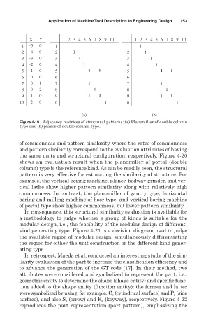
Figure 4-19 Adjacency matrices of structural patterns: (a) Planomiller of double column
type and (b) planer of double column type.
of commonness and pattern similarity, where the rates of commonness
and pattern similarity correspond to the evaluation attributes of having
the same units and structural configuration, respectively. Figure 4-20
shows an evaluation result when the planomiller of portal (double
column) type is the reference kind. As can be readily seen, the structural
pattern is very effective for estimating the similarity of structure. For
example, the vertical boring machine, planer, bedway grinder, and ver-
tical lathe show higher pattern similarity along with relatively high
commonness. In contrast, the planomiller of gantry type, horizontal
boring and milling machine of floor type, and vertical boring machine
of portal type show higher commonness, but lower pattern similarity.
In consequence, this structural similarity evaluation is available for
a methodology to judge whether a group of kinds is suitable for the
modular design, i.e., the feasibility of the modular design of different-
kind generating type. Figure 4-21 is a decision diagram used to judge
the available region of modular design, simultaneously differentiating
the region for either the unit construction or the different-kind gener-
ating type.
In retrospect, Maeda et al. conducted an interesting study of the sim-
ilarity evaluation of the part to increase the classification efficiency and
to advance the generation of the GT code [17]. In their method, two
attributes were considered and symbolized to represent the part, i.e.,
geometric entity to determine the shape (shape entity) and specific func-
tion added to the shape entity (function entity): the former and latter
were symbolized by using, for example, C (cylindrical surface) and P (side
e
e
surface), and also S (screw) and K (keyway), respectively. Figure 4-22
e
e
reproduces the part representation (part pattern), emphasizing the