
Page 192 - Modular design for machine tools
P. 192
152 Modular Design Guide and Machine Tools Description
8 6 5 4 3 2 1 (I)
M M M M M M M
6 10 (III)
S S
7 5 4 3 2 1 (II)
M M M M M M
9 10 (IV)
S S A rooted directed tree
(0, 2)
Y (b)
(0, 2)
X
(–4, 0) (0, 0) (2, 0)
(a)
(–5, 0) (0, 0) (2, 0)
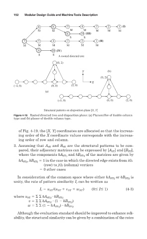
Structural patterns on disposition plane [X, Y]
Figure 4-18 Rooted directed tree and disposition plane: (a) Planomiller of double column
type and (b) planer of double column type.
of Fig. 4-19, the [X, Y] coordinates are allocated so that the increas-
ing order of the X coordinate values corresponds with the increas-
ing order of row and column.
3. Assuming that A ST and B ST are the structural patterns to be com-
pared, their adjacency matrices can be expressed by [A ] and [B ],
ST
ST
where the components
A STij and
B STij of the matrices are given by
A STij ,
B STij 1 in the case in which the directed edge exists from ith
(row) to jth (column) vertices
0 other cases
In consideration of the common space where either
A STij or
B STij is
unity, the rate of pattern similarity I can be written as
r
I u /(u ST v ST w ST ) (0 I 1) (4-3)
ST
r
where u ST
A STij
B STij
v
A STij (1
B STij )
w (1
A STij )
B STij
Although the evaluation standard should be improved to enhance reli-
ability, the structural similarity can be given by a combination of the rates