Page 191 - Modular design for machine tools
P. 191

Application of Machine Tool Description to Engineering  Design    151

                            Y   X  Y
                         X s  s  s  s

                Set X                   Set Y
                    s
                        X s        Y s     s
                        X s        Y s


                            R(X )
                               s
                     x 1              y y 1
                 X s  x 2             y 2  Y s
                 X s  x 3             y 3  Y s
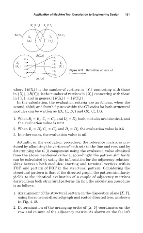
                     x 4              y 4      Figure 4-17    Definition of rate of
                     x 5              y 5 6    commonness.
                            R(Y )
                               s

               where |R(X )| is the number of vertices in |Y | connecting with those
                                                          s
                          s
               in |X |, |R(Y )| is the number of vertices in |X | connecting with those
                            s
                    s
                                                          s
               in |Y |, and in general |R(X )|   |R(Y )|.
                    s
                                                    s
                                          s
                 In the calculation, the evaluation criteria are as follows, when the
               second, third, and fourth figures within the GT codes for both structural
               modules can be written as (B , C , D ) and (B
, C
, D
).
                                                         s
                                             s
                                          s
                                                            s
                                                 s
                                                               s
               1. When B   B
, C   C
, and D   D
, both modules are identical, and
                                 s
                         s
                              s
                                                  s
                                             s
                                      s
                  the evaluation value is unit.
               2. When B   B
, C   C
, and D   D
, the evaluation value is 0.5
                                      s
                                 s
                              s
                         s
                                              s
                                                   s
               3. In other cases, the evaluation value is nil.
                 Actually, in the evaluation procedure, the reference matrix is pro-
               duced by allocating the vertices of both sets to the line and row, and by
               determining the (i, j) component using the evaluated value obtained
               from the  above-mentioned criteria, accordingly, the pattern similarity
               can be calculated by using the information for the adjacency relation-
               ships between both modules, starting and terminal vertices within
               FOF, and pattern of FOF in the structural pattern. Considering the
               structural pattern is that of the directed graph, the pattern similarity
               yields to the identical evaluation of a couple of adjacency matrices
               derived from both structural patterns. In fact, the calculation procedure
               is as follows.
               1. Arrangement of the structural pattern on the disposition plane [X, Y],
                  using the converse directed graph and  rooted-directed tree, as shown
                  in Fig. 4- 18.
               2. Determination of the arranging order of [X, Y] coordinates on the
                  row and column of the adjacency matrix. As shown on the far left
   186   187   188   189   190   191   192   193   194   195   196