
Page 261 - Modular design for machine tools
P. 261
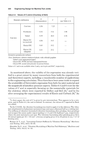
220   Engineering Design for Machine Tool Joints

               TABLE 6-3 Values of C and m (Courtesy of Bell)

                                             m                     C
                     Material combination               C
                                        (dimensionless)        (per Table 6-2)
                              Cast iron     0.50       7.25        —

                             Ferobestos     0.32      43.6         3.98
                               Tufnol       0.39      26.0         2.36
                 Cast iron
                             Glacier DU     0.50      19.5
                             (as received)                         —
                             Glaxier DX     0.43      19.2         —
                             Glacier DX     0.41      25.2         —
                              (dimpled)
                Ground-to-ground joint surfaces
                Note: Ferobestos: asbestos reinforced plastic with colloidal graphite
                          Tufnol: resin-impregnated paper.
                          Glacier DU: PTFE and lead-impregnated bronze.
                          Glacier DX: acetal resin polymer on porous bronze.
                                                          2
               Values of C and m are available when l and p are in min and lb/in , respectively.
                 As mentioned above, the validity of the expression was already veri-
               fied to a great extent by many researchers from both the experimental
               and theoretical aspects, including a considerable number of applications
               to the engineering calculation. Thus there have been some trials to expand
               the availability of Ostrovskii’s expression from both the joint material and
               the magnitude of interface pressure aspects. Tables 6-3 and 6-4 are for the
               values of C and m especially focusing on the nonmetallic materials for
                                                                     5
               the slideway, which were reported by Dolbey and Bell [8], and by Ito
                                                                             6
               after arranging the experimental results of Eisele and Corbach [9]. As

                 5
                  In their paper, the unit of C is given by  in (microinches). This appears to be a mis-
               print, and in Table 6-3, the unit is deleted. In contrast, the values of C reported by Back
               are added.
                 6
                  In the U.S.S.R., the vibratory burnishing was tried to apply it to the slideway. The vibra-
               tory attachment is of planetary movement type and uses a diamond ball as a cutting tool.
               The stiffness of vibratory burnished (vibratory burnishing after grinding, then grinding)
                                                                  2
               and scraped flat joints under repeat loading is 1.5 and 0.83 (kgf/mm )  m, respectively,
               where the joint material is cast iron. The vibratory burnishing after grinding gives 35 to
                                                                              2
                                        2
               46 contact spots per 25   25 mm , whereas scraping gives 24 to 36 points in any 1 in of
               bearing area.
                 Ryzhov, E. V., et al., “Increasing Contact Stiffness by Vibratory Burnishing,” Machines
                 and Tooling, 1972, 43(1): 59–60.
                 Shneider, Yu G., et al., “Vibratory Burnishing of Machine Tool Slideways,” Machines and
                 Tooling, 1972, 43(11): 51–52.