
Page 266 - Modular design for machine tools
P. 266
Engineering Design Fundamentals and Single Flat Joint Characteristics 225
M
P
150
0.08
Interface pressure
0.07 p = 0.55 kgf/cm 2
0.06
2.15
1.1 kgf/cm 2 4.15
0.05
φ, m m/cm 0.04 6.8
10.2
0.03 13.5
0.02
0.01
0
100 200 300 400
.
M, kgf cm
Note: The joint has a rectangular shape, both faces are hand-scraped, both elements are
made of cast iron.
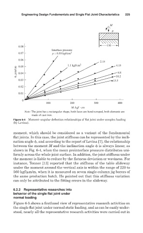
Figure 6-4 Moment–angular deflection relationships of flat joint under complex loading
(by Levina).
moment, which should be considered as a variant of the fundamental
flat joints. In this case, the joint stiffness can be represented by the incli-
nation angle , and according to the report of Levina [7], the relationship
between the moment M and the inclination angle is always linear, as
shown in Fig. 6-4, when the mean preinterface pressure distributes uni-
formly across the whole joint surface. In addition, the joint stiffness under
the moment is liable to reduce by the flatness deviation or waviness. For
instance, Tenner [13] reported that the stiffness of the table slideway
under the moment around the vertical axis is within the range of 220 to
560 kgf/ m/m, when it is measured on seven single-column jig borers of
the same production batch. He pointed out that this stiffness variation
can only be attributed to the fitting errors in the slideway.
6.2.2 Representative researches into
behavior of the single flat joint under
normal loading
Figure 6-5 shows a firsthand view of representative research activities on
the single flat joint under normal static loading, and as can be easily under-
stood, nearly all the representative research activities were carried out in