
Page 118 - Book Hosokawa Nanoparticle Technology Handbook
P. 118
FUNDAMENTALS CH. 2 STRUCTURAL CONTROL OF NANOPARTICLES
References
[1] M. Naito: Kagaku Kougaku no Shimpo 30 (Progress of
Chemical Engineering), in Biryushi Seigyo (Fine
Particle Control), Maki-Shoten, p. 69 (1996).
[2] M. Naito, A. Kondo and T. Yokoyama: ISIJ Int., 33,
915–924 (1993).
[3] M. Naito, T. Hatta, S. Asahi, T. Tanimoto and S. Endo:
Kagaku Kogaku Ronbunshu, 24, 99–103 (1998).
[4] K. Nogi, M. Naito, A. Kondo, A. Nakamura, K. Niihara
and T. Yokoyama: Powder and Powder Metal., 43,
396–401 (1996).
[5] M. Naito: Nanoparticle Technol., The Nikkan Shimbun,
Ltd., p. 159 (2003).
[6] H. Abe, I. Abe, K. Sato and M. Naito: J. Am. Ceram.
1μm
Soc., 88, 1359–1361 (2005).
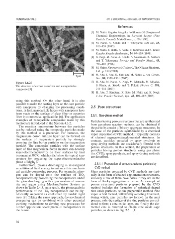
Figure 2.4.25 [7] H. Abe, M. Naito, K. Nogi, M. Matsuda, M. Miyake,
The structure of carbon nanofiber and nanoparticles S. Ohara, A. Kondo and T. Fukui: Phisica C, 391,
composite [5]. 211–216 (2003).
[8] H. Abe, T. Kimitani, K. Sato, M. Naito and K. Nogi:
J. Soc. Powder Technol., Jpn., 42, 409–412 (2005).
using this method. On the other hand, it is also
possible to make the coating layer on the core particle
with nanopores by changing the processing condi- 2.5 Pore structure
tions. In fact, nanoparticle layers with nanopores have
been made on the surface of glass fiber or ceramics
fiber in commercial applications [6]. The application 2.5.1. Gas-phase method
examples of nanoparticle composites made by this Particles having porous structures that are synthesized
method are introduced in the Section 4.3.2. from gas-phase reaction methods can be obtained if
The reaction temperature between the particles the particles consist of blocky aggregate structures. In
can be reduced using the composite particles made the case of the particles synthesized by a chemical
by this method as a precursor. For instance, the vapor deposition (CVD) method, it typically consists
magnesium–boron mixture layer can be formed on of chained aggregated/agglomerated structures. In
the surface of magnesium particle by strongly contrast, particles prepared by spray pyrolysis or
pressing the fine boron particles on the magnesium spray-drying methods are occasionally formed with
particle. The composite particles with the surface porous structures. In this section, the preparation of
layer of fine magnesium–boron mixture can develop particles having porous structures using gas phase
super-electroconductivity on their surfaces by heat (i.e. CVD), spray pyrolysis, and spray-drying methods
treatment at 500 C, which is far below the typical tem- are described.
perature for producing the super-electroconductive
phase of MgB [7].
2
Furthermore, plasma discharging is investigated 2.5.1.1 Preparation of porous structured particles by
as additional field energy to enhance this mechani- CVD method
cal particle-composing process. For example, nitro- Many particles prepared by CVD methods are typi-
gen can be doped onto the surface of TiO 2 cally in the form of chained agglomeration structures,
nanoparticles by processing the nanoparticles under and only a few of them have pores if they are in the
the glow discharging with a gas mixture of ammo- form of blocky aggregation structure. An example of
nia and argon using MechanoFusion System as porous structured particles prepared by the CVD
shown in Table 2.4.3. As a result, the photocatalytic method includes the formation of spherical-shaped
performance of the TiO nanoparticles can be sig- zinc oxide particles. As the preparation method, zinc
2
nificantly improved as confirmed by visible light vapor is first formed, followed by a cooling treatment,
tests [8]. Taking the same approach, the mechanical during which, zinc particles are formed. In the next
processing can be combined with other potential process, only the surface of the zinc particles are oxi-
working mechanisms to develop new processes for dized to form a zinc oxide layer, and finally the ele-
further application development of nanoparticles in mental zinc is removed to obtain zinc oxide cage
the future. particles, as shown in Fig. 2.5.1 [1].
94