
Page 364 - Book Hosokawa Nanoparticle Technology Handbook
P. 364
FUNDAMENTALS CH. 6 EVALUATION METHODS FOR PROPERTIES OF NANOSTRUCTURED BODY
5 1.0
Temperature rise, T/ T 0.5
4
Temperature rise, T/ T 3 2 0.0 0.0 t 1/2 0.1388 0.4 Time, t/ 0.6 0.8 1.0
0.2
Heated face
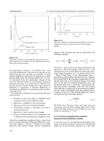
Figure 6.3.4
Half time method to calculate thermal diffusivity from the
1
temperature change of specimen rear face after pulse
heating.
Opposite face
0
0.0 0.2 0.4 0.6 0.8 1.0
change of the specimen rear face is expressed by the
Fourier number, t/ 0 following equation:
Figure 6.3.3
Temperature changes at the front face and rear face of a ⎡ ⎛ t ⎞ ⎤
n
T 1
⎜
⎟
planar specimen as a function of the nondimensional time Tt() ⎢ ⎢ 2 ∑ ( 1 ) exp ( n) 2 ⎠ ⎥ ⎥ (6.3.3)
⎝
after uniform pulse heating. ⎣ n 1 0 ⎦
where T Q/C, Q the total energy absorbed by the
specimen, C the heat capacity of the specimen, the
0
the temperature change of the heated face. And characteristic time of heat diffusion across the speci-
since the temperature of the rear face opposite to the men. Graph of equation (6.3.3) is shown in Fig. 6.3.4.
heated face increases quickly for materials of large When 0.1388 times of the characteristic time
thermal diffusivity and slowly for materials of small passed after pulse heating, specimen rear face tempera- 0
thermal diffusivity, the thermal diffusivity can also ture reached half of the maximum temperature rise. The
be calculated from the temperature change of the characteristic time is determined by fitting a theoretical
rear face. Because speed of a temperature change of curve to the rear face transient temperature curve, and
specimen rear face is in proportion to a thermal dif- the thermal diffusivity is calculated. Conventional stan-
fusivity and is in inverse proportion to the square of dard data analysis algorithm is the half time method
thickness of specimen, a thermal diffusivity is where the time reaching half of the maximum tempera-
calculated by thickness of specimen and heat diffu- ture rise value is determined from the measured curve,
sion time [1,5]. as shown in Fig. 6.3.4. The thermal diffusivity value is
The following conditions are assumed for the ideal
measurement: calculated from the following equation:
1. Duration of the laser pulse is negligibly short 0 1388d 2
.
(6.3.4)
compared with the heat diffusion time. t 12
2. Specimen is adiabatic to the environment.
3. Specimen front face is heated uniformly. Nd-YAG laser, Nd glass laser and ruby laser are
4. Temperature change of specimen rear face is commonly used for pulse heating light source. Pulse
duration of light emission is from 100 s to 1ms, and
measured precisely.
energy of one pulse is 1–10J.
5. Specimen is dense, uniform and opaque.
6. Change of thermal diffusivity by temperature rise
of specimen after pulse heating is negligibly small. 6.3.2 Front-face heating/front-face detection
picosecond thermoreflectance method
Under the assumptions mentioned above, when front
face of a planar specimen of thermal diffusivity
, spe- It was not easy by conventional measurement tech-
cific heat capacity c, density , thickness d is heated nique to determine thermal conductivity and thermal
pulsewise with uniform energy density; temperature diffusivity in the thickness direction of a thin film
338