
Page 46 - Book Hosokawa Nanoparticle Technology Handbook
P. 46
1.7 COMPOSITE STRUCTURE FUNDAMENTALS
The values of t, r and r as a function of P/P can [8] C. Orr Jr., J.M. DallaValle: Fine Particle Measurement,
s
k
p
be calculated by using a combination of equa- Macmillan Inc., p. 271 (1959).
tions 1.6.8 and 1.6.9. [9] R.W. Craust, F.F.A. Inkley: Advance in Catalysis 9,
Supposing total pore volume V , which is expressed as Academic Press Inc., New York, p. 143 (1957).
p
a liquid volume equivalent to adsorbed amount at P ,
s
and adsorbed amount V at a pressure P (also as an
equivalent liquid volume), V V is considered as a total 1.7 Composite structure
p
empty pore volume that is generated by evaporation tak-
ing place at pores having radius less than r while the
p
pressure is reduced from P to P. This is given by 1.7.1 Composite structure of nanoparticle
s
the following equation:
A peculiar characteristic of the nanoparticle appears by
the effect of size that is the general structure factor of
2
V V ∫ ( r t L r dr (1.6.10) particle. For example, basic physical properties such as
)
(
)
melting point and boiling point drop by the super-
p
miniaturization. Various functions such as activity of
r p
catalyst are also improved by the nanosize effect.
where L(r) is a total length of pore with radius r. V p However, the cohesion of the nanoparticle remarkably
and V are obtained from adsorption data, and r and t increases with increase in the surface energy of particle
p
can be determined with respect to P/P . However, L(r) by the nanosize effect, and the strong cohesion
s
has to be obtained for each r. decreases the handling character of the nanoparticle.
For this reason, Wheeler has analyzed L(r) with the One useful method that improves handling character of
assumption that its distribution follows Maxwell’s or nanoparticles is to apply the composite structure such
Gaussian distribution. as surface modification using nanoparticles. The com-
Thereafter, Barrett–Joyner–Halenda [6] have sug- posite structural control such as surface modification
gested a method that uses numerical integration with- will reduce the cohesive property of nanoparticels, and
out assuming any specific distribution, which is the function of nanoparticles will appear smoothly. In
called BJH method. Since then this method has been addition, the composite structure that is formed by
improved by Pierece [7], Orr-Dalla Vallue [8], and some kinds of nanoparticles will be able to combine
Crauston-Inkley [9]. some kinds of function, and it expects that new func-
The measurement of pore size distribution using the tion will appear by the effect combined some kinds of
gas adsorption method would have a problem in appli- function of nanoparticle. The composite structure can
cation of the Kelvin equation to pore radius less than be roughly classified as follows: (1) the composite
1nm. Also, because measurement of relative pressure structure using nanoparticles, (2) the composite struc-
around saturation level is difficult and making some ture formed by agglomeration of nanoparticles, and (3)
assumptions cannot be avoided for analyzing data, the composite body fabricated with nanoparticles.
pore size distribution only less than 30nm can be usu- The size of the nanoparticle is defined from single
ally measured. Therefore, use of mercury intrusion nano (less than 10nm) to about 100nm in the narrower
porosimetry in combination with the gas adsorption sense, and also to a few 100nm in the wider sense. In
method is preferable for measuring a wide range of this chapter, the composite structure is assumed to be
pore size distribution.
classified by the wide-range definition (from single
nano to few 100nm). Table 1.7.1 and Fig.1.7.1 show
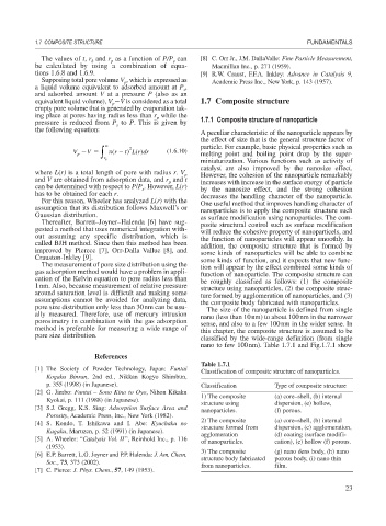
References
Table 1.7.1
[1] The Society of Powder Technology, Japan: Funtai
Classification of composite structure of nanoparticles.
Kogaku Binran, 2nd ed., Nikkan Kogyo Shimbun,
p. 355 (1998) (in Japanese). Classification Type of composite structure
[2] G. Jimbo: Funtai – Sono Kino to Oyo, Nihon Kikaku
1) The composite (a) core–shell, (b) internal
Kyokai, p. 111 (1988) (in Japanese).
structure using dispersion, (e) hollow,
[3] S.J. Gregg, K.S. Sing: Adsorption Surface Area and
nanoparticles. (f) porous.
Porosity, Academic Press, Inc., New York (1982).
2) The composite (a) core–shell, (b) internal
[4] S. Kondo, T. Ishikawa and I. Abe: Kyuchaku no
structure formed from dispersion, (c) agglomeration,
Kagaku, Maruzen, p. 52 (1991) (in Japanese).
agglomeration (d) coating (surface modifi-
[5] A. Wheeler: “Catalysis Vol. II ”, Reinhold Inc., p. 116
of nanoparticles. cation), (e) hollow (f) porous.
(1953).
3) The composite (g) nano dens body, (h) nano
[6] E.P. Barrett, L.G. Joyner and P.P. Halenda: J. Am. Chem.
structure body fabricated porous body, (i) nano thin
Soc., 73, 373 (2002).
from nanoparticles. film.
[7] C. Pierce: J. Phys. Chem., 57, 149 (1953).
23