
Page 48 - Book Hosokawa Nanoparticle Technology Handbook
P. 48
1.7 COMPOSITE STRUCTURE FUNDAMENTALS
forms observation ultrathin flake of the sample ultramicrotomy is most effective. An ultramicrotome
embedded in epoxy resin etc. by cutting, (5) Ion is used for the ultramicrotomy, and can prepare an
milling method that forms observation side of the ultrathin flake of a thickness less than 100nm. The
sample or the sample embedded in resin using ion sample such as powder is embedded in epoxy resin
beam, (6) Etching method with which observation side etc. The sample embedded in a resin is driven with a
is formed by etching of bulk sample. Embedding, predefined thickness in each step continuously, and
ultramicrotomy, ion milling and etching are effective cut repeatedly with a knife to obtain the ultrathin
methods for observing the internal microstructure. In- flake. The thickness of ultrathin flake can be con-
depth knowledge of the sample and skill are required trolled by either thermal expansion or accurate
to prepare a proper sample for the observation. mechanical drive. For obtaining a proper ultrathin
SEM is a method of irradiating the electron beam to flake in which the embedded particles are not sepa-
the sample, and obtaining the observation image based rated from the resin or destroyed, it is important to
on the generated second electron beam. For SEM match hardness of both the particle sample and the
observation, conductivity is necessary for the sample, resin, and to select material of the knife used for cut-
and the conductive thin film of gold etc. is formed by ting. There are glass, sapphire, and diamond as a knife
sputtering on the surface of the insulation material. material. The glass is used for the knife to cut the soft
There is little shape restriction in the sample, and an material such as biomechanical materials, and the
easy and effective evaluation is possible. Field emission sapphire and diamond are used to cut hard materials
type SEM can observe at a high magnification of about such as ceramics and metals.
300,000 times, and can observe nanosize microstruc-
ture. On the other hand, TEM is a method of obtaining
observation images through the sample using the trans- 1.7.3 Microstructure evaluation of several types
mission electron beam, and then the thickness of the of nano composite particles
sample greatly influences the observation. It is neces-
sary for the TEM observation that the sample thickness Some examples of the composite structure evaluation
is less than 100nm, and the sample preparation plays a of typical nanoparticles by TEM and SEM are intro-
very important role. Both SEM and TEM can set up duced below.
energy dispersive spectrometer (EDS), which enable the
elemental analysis at the observation point in addition to (1) Nano particle coating (Core-partial shell) composite
the shape and microstructure observation. The EDS is a structure [1, 2, 3]
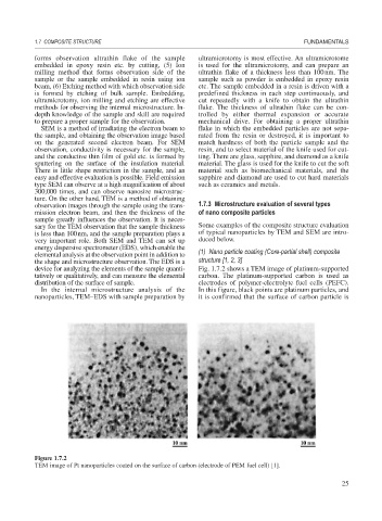
device for analyzing the elements of the sample quanti- Fig. 1.7.2 shows a TEM image of platinum-supported
tatively or qualitatively, and can measure the elemental carbon. The platinum-supported carbon is used as
distribution of the surface of sample. electrodes of polymer-electrolyte fuel cells (PEFC).
In the internal microstructure analysis of the In this figure, black points are platinum particles, and
nanoparticles, TEM–EDS with sample preparation by it is confirmed that the surface of carbon particle is
Figure 1.7.2
TEM image of Pt nanoparticles coated on the surface of carbon (electrode of PEM fuel cell) [1].
25