
Page 49 - Book Hosokawa Nanoparticle Technology Handbook
P. 49
FUNDAMENTALS CH. 1 BASIC PROPERTIES AND MEASURING METHODS OF NANOPARTICLES
defined as a novel method to create chemical bonds
between particles in dry process without any binder.
In this figure, surface fine particles with a size of
about 100nm are YSZ, and core particles are NiO. It
is confirmed from this figure that fine YSZ particles
partially cover the surface of NiO particles. In short,
the core–shell structure, actually core-partial shell
structure, has been made.
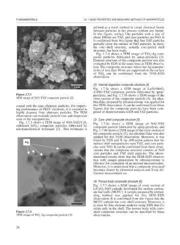
Fig. 1.7.4 shows a TEM image of TiO -Ag com-
2
posite particles fabricated by spray-pyrolysis [3].
Element structure of this composite particle was also
evaluated by EDS at the same time as TEM observa-
tion. The composite structure where the Ag nanopar-
ticles of less than 10nm are supported on the surface
of TiO can be confirmed from the TEM–EDS
2
observation.
(2) Internal dispersion composite structure [4]
1 μm
Fig. 1.7.5a shows a SEM image of La(Sr)MnO 3
(LSM)-YSZ composite particle fabricated by spray-
Figure 1.7.3 pyrolysis, and Fig. 1.7.5b shows a TEM image of the
SEM image of NiO-YSZ composite particle [2]. cross section of the composite particle [4]. An ultra-
thin flake prepared by ultramicrotomy was applied for
coated with the nano platinum particles. For improv- this TEM observation. It can be confirmed from these
ing performance of PEFC electrode, it is essential to figures that the composite particles have been com-
highly disperse finer platinum particles. The TEM posed of dispersed nano LSM and YSZ particles.
observation can evaluate particle size and dispersion
state of the nanoparticles. (3) Core–shell composite structure [5]
Fig. 1.7.3 shows a TEM image of NiO-YSZ(Y O 3 Fig. 1.7.6a shows a SEM image of NiO-YSZ
2
stabilized ZrO ) composite particles fabricated by composite particle fabricated by spray-pyrolysis, and
2
mechanochemical technique [2] . This technique is
Fig. 1.7.6b shows a TEM image of the cross section of
the composite particle [5]. An ultrathin flake was also
applied for this TEM observation. Moreover, it was
found by EDS and X-ray diffraction pattern that the
Ag
A g
surface shell nanoparticles were YSZ, and core parti-
cles were NiO. It can be confirmed from these obser-
vations that the composite structure consists of NiO
core particles and YSZ shell particles. The above-
mentioned results show that the TEM–EDS observa-
tion with sample preparation by ultramicrotomy is
effective for evaluation of an internal microstructure.
Moreover, it is understood that a composite structural
becomes clearer by elemental analysis and X-ray dif-
fraction measurement etc.
(4) Porous body composite structure [6]
Fig. 1.7.7 shows a SEM image of cross section of
LiCoO -NiO cathode developed for molten carbon-
2
ate fuel cells (MCFC). A sample prepared by embed-
ding method was applied for this SEM–EDS
observation. It is confirmed from this figure that the
10nm MCFC cathode has core–shell structure. Moreover, it
is clear by line element analysis using EDS that Co
exists only in the shell. The porous body with core–
Figure 1.7.4 shell composite structure can be specified by these
TEM image of TiO -Ag composite particle [3]. observations.
2
26