
Page 602 - Book Hosokawa Nanoparticle Technology Handbook
P. 602
APPLICATIONS 36 DEVELOPMENT OF A HIGH-PERFORMANCE SECONDARY BATTERY
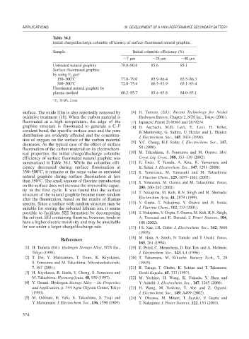
Table 36.1
Initial charge/discharge columbic efficiency of surface fluorinated natural graphite.
Sample Initial columbic efficiency (%)
7 m 25 m 40 m
Untreated natural graphite 79.8–80.8 85.6 85.1
Surface fluorinated graphite
by using F gas a
2
150–300 C 77.0–79.0 85.9–86.4 85.5–86.3
300–500 C 72.0–75.4 66.5–83.9 65.1–83.4
Fluorinated natural graphite by
plasma method 80.2–85.7 85.4–85.8 84.0–85.1
a F 2 : 30 kPa, 2 min.
surface. The oxide film is also reportedly removed by [6] H. Tamura (Ed.): Recent Technology for Nickel
oxidative treatment [18]. When the carbon material is Hydrogen Battery, Chapter 2, NTS Inc., Tokyo (2001).
fluorinated at a high temperature, the edge of the [7] Japanese Patent 2140564 and 2679274.
graphite structure is fluorinated to generate a C–F [8] D. Aurbach, M.D. Levi, E. Levi, H. Teller,
covalent bond, the specific surface area and the pore B. Markovsky, G. Salitra, U. Heider and L. Heider:
distribution are evidently affected and the concentra- J. Electrochem. Soc., 145, 3024 (1998).
tion of oxygen on the surface of the carbon material [9] Y.C. Chang, H.J. Sohn: J. Electrochem. Soc., 147,
decreases. As the typical case of the effect of surface
fluorination of the carbon material on its electrochem- 50 (2000).
ical properties, the initial charge/discharge columbic [10] M. Takashima, S. Yonezawa and M. Ozawa: Mol.
efficiency of surface fluorinated natural graphite was Cryst. Liq. Cryst., 388, 153–159 (2002).
summarized in Table 36.1. While the columbic effi- [11] E. Endo, T. Yasuda, A. Kita, K. Yamamura and
ciency decreased during surface fluorination at K. Sekai: J. Electrochem. Soc., 147, 1291 (2000).
350–500 C, it remains at the same value as untreated [12] S. Yonezawa, M. Yamasaki and M. Takashima:
natural graphite during surface fluorination at less J. Fluorine Chem., 125, 1657–1661 (2005).
than 350 C. The small amount of fluorine introduction [13] S. Yonezawa, M. Ozawa and M. Takashima: Tanso,
on the surface does not increase the irreversible capac- 205, 260–262 (2002).
ity in the first cycle. It was found that the surface [14 T. Nakajima, M. Koh, R.N. Singh and M. Shimada:
structure of the natural graphite became more random
after the fluorination, based on the results of Raman Electrochim. Acta, 44, 2879 (1999).
spectra. Since a surface with random structure may be [15] V. Gupta, T. Nakajima, Y. Ozawa and H. Iwata:
suitable for storing the solvated lithium ion, it seems J. Fluorine Chem., 112, 233 (2001).
possible to facilitate SEI formation by decomposing [16] T. Nakajima, V. Gupta, Y. Ozawa, M. Koh, R.N. Singh,
the solvent. SEI containing fluorine, however, tends to A. Tressaud and E. Durand: J. Power Sources, 104,
have a higher electric resistivity and may be unsuitable 108 (2002).
for use under a larger charge/discharge rate. [17] J.S. Xue, J.R. Dahn: J. Electrochem. Soc., 142, 3668
(1995).
[18] M. Hara, A. Satoh, N. Tamaki and T. Osaki: Tanso,
References
165, 261 (1994).
[1] H. Tamura (Ed.): Hydrogen Storage Alloy, NTS Inc., [19] E. Peled, C. Menachem, D. Bar-Tow and A. Melman:
Tokyo (1998). J. Electrochem. Soc., 143, L4 (1996).
[2] T. Ibe, Y. Matsumura, T. Ueno, K. Kiyokawa, [20] T. Takamura, M. Kikuchi: Battery Tech., 7, 29
S. Yonezawa and M. Takashima: Nihonkaakukaioshi, (1995).
7, 387 (2001). [21] R. Takagi, T. Okubo, K. Sekine and T. Takamura:
[3] H. Kiyokawa, R. Ikeda, Y. Chong, S. Yonezawa and Denki Kagaku, 65, 333 (1997).
M. Takashima: Hyomengijyutu, 48, 939 (1997). [22] M. Yoshino, H. Wang, K. Fukuda, Y. Hara and
[4] Y. Osumi: Hydrogen Storage Alloy – Its Properties Y. Adachi: J. Electrochem. Soc., 147, 1245 (2000).
and Application, p. 144 Agne Gijyutu Center, Tokyo [23] H. Wang, M. Yoshino, T. Abe and Z. Ogumi:
(1993). J. Electrochem. Soc., 149, A499 (2002).
[5] M. Oshitani, H. Yufu, K. Takashima, S. Tsuji and [24] Y. Ohzawa, M. Mitani, T. Suzuki, V. Gupta and
Y. Matsumaru: J. Electrochem. Soc., 136, 1590 (1989). T. Nakajima: J. Power Sources, 122, 153 (2003).
574