
Page 127 - Neural Network Modeling and Identification of Dynamical Systems
P. 127
116 3. NEURAL NETWORK BLACK BOX APPROACH TO THE MODELING AND CONTROL OF DYNAMICAL SYSTEMS
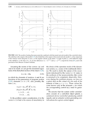
FIGURE 3.14 The results of testing the neurocontroller combined with the neural network model of the controlled object.
The solid line is the output of the model (3.25); the dotted line is the output of the neural network model; V z is the component
of the velocity vector along the Oz-axis; q is the angular velocity of the pitch; θ is angle of pitch; δ e is the deflection angle
(ref ) (ref )
of the stabilizer; t is the time; EV y , Eq are the differences |V z − V z | and |q − q |, respectively (From [99], used with
permission from Moscow Aviation Institute).
Assuming the norms of the vectors ||x|| and the choice of the operation mode of the dynam-
||u|| to be small, we can get the linearized equa- ical system, i.e., source of its multimode behav-
tions of the disturbed motion of the object (3.28), ior. We need to clarify the nature of the uncer-
tainty introduced by the vector λ ∈ .Later,in
˙ x = Ax + Bu, (3.31)
the synthesis of the neurocontroller, this vector
in which the elements of matrices A and B are is assumed to be completely observable. How-
functions of the parameters of program motion ever, during the synthesis process, we have no
s
(3.29), elements λ ∈ ⊂ R , and, possibly, the a priori data on the values of λ for each of the
time t, i.e., instants of time t 0 t i t f . These values be-
come known only at the moment t i ,forwhich
0
0
||a ij || = ||a i,j ( x , u ,λ,t)||,
the corresponding control u(t i ) must be gener-
0
0
||b ik || = ||b i,k ( x , u ,λ,t)||, ated.
i,j ∈{1,...,n}, We assume that the system under consider-
ation consists of a controlled object (plant), a
k ∈{1,...,m},
command device (controller) producing control
In the problem under consideration, it is the signals, and an actuator system generating con-
vector λ ∈ that is the source of uncertainty in trol actions for a given control signal.