
Page 165 - Numerical Analysis and Modelling in Geomechanics
P. 165
146 C.L.RAMSHAW AND A.R.SELBY
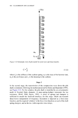
Figure 5.12 Schematic view of pile model for axial wave and shear transfer.
(5.12)
where k is the stiffness of the cushion spring, m is the mass of the hammer ram,
c
r
m is the anvil mass and c is the damping in the cushion.
c
a
Stage 2
In the second stage, the transmission of the compression wave down the pile
shaft is simulated, following the method proposed by Deeks and Randolph (1995),
see Figure 5.12. For the solution, the pile shaft is modelled by an axisymmetric
mesh of 8-noded finite elements. A mass-spring-dashpot represents the toe
resistance, (Wolf, 1988; Decks, 1992). A series of springs and dampers is
sufficient to model the shaft/soil interface, for this stage, which can transmit
shear-waves independent of frequency. Excitation is imposed as a force-time
function, and the required ‘solution’ is the force-time functions at each of the shaft
spring-dampers, and at the toe, with respective time delays.