
Page 163 - Numerical Analysis and Modelling in Geomechanics
P. 163
144 C.L.RAMSHAW AND A.R.SELBY
Figure 5.9 Schematic of response of a FE/IE mesh to geostatic self-weight. (Actual FE
mesh was 50×50 or more.)
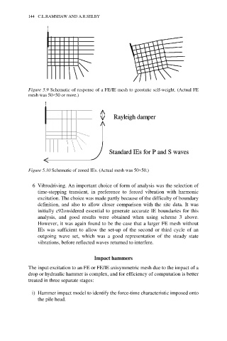
Figure 5.10 Schematic of zoned IEs. (Actual mesh was 50×50.)
6 Vibrodriving. An important choice of form of analysis was the selection of
time-stepping transient, in preference to forced vibration with harmonic
excitation. The choice was made partly because of the difficulty of boundary
definition, and also to allow closer comparison with the site data. It was
initially c92onsidered essential to generate accurate IE boundaries for this
analysis, and good results were obtained when using scheme 3 above.
However, it was again found to be the case that a larger FE mesh without
IEs was sufficient to allow the set-up of the second or third cycle of an
outgoing wave set, which was a good representation of the steady state
vibrations, before reflected waves returned to interfere.
Impact hammers
The input excitation to an FE or FE/IE axisymmetric mesh due to the impact of a
drop or hydraulic hammer is complex, and for efficiency of computation is better
treated in three separate stages:
i) Hammer impact model to identify the force-time characteristic imposed onto
the pile head.