
Page 164 - Numerical Analysis and Modelling in Geomechanics
P. 164
MODELLING OF GROUND WAVES 145
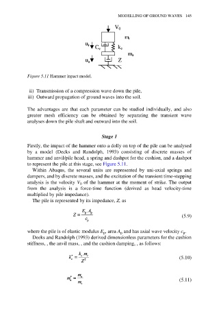
Figure 5.11 Hammer inpact model.
ii) Transmission of a compression wave down the pile,
iii) Outward propagation of ground waves into the soil.
The advantages are that each parameter can be studied individually, and also
greater mesh efficiency can be obtained by separating the transient wave
analyses down the pile shaft and outward into the soil.
Stage 1
Firstly, the impact of the hammer onto a dolly on top of the pile can be analysed
by a model (Decks and Randolph, 1993) consisting of discrete masses of
hammer and anvil/pile head, a spring and dashpot for the cushion, and a dashpot
to represent the pile at this stage, see Figure 5.11.
Within Abaqus, the several units are represented by uni-axial springs and
dampers, and by discrete masses, and the excitation of the transient time-stepping
analysis is the velocity V 0 of the hammer at the moment of strike. The output
from the analysis is a force-time function (derived as head velocity-time
multiplied by pile impedance).
The pile is represented by its impedance, Z, as
(5.9)
where the pile is of elastic modulus E , area A and has axial wave velocity c .
p
p
p
Deeks and Randolph (1993) derived dimensionless parameters for the cushion
stiffness, , the anvil mass, , and the cushion damping, , as follows:
(5.10)
(5.11)