
Page 159 - Numerical Analysis and Modelling in Geomechanics
P. 159
140 C.L.RAMSHAW AND A.R.SELBY
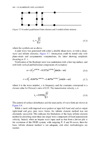
Figure 5.5 8-noded quadrilateral finite element and 5-noded infinite element.
(5.5)
where the symbols are as above.
A pure wave was generated with either a double shear-wave, or with a shear-
wave and infinite elements, Figure 5.7. Attenuation could be tested only with
plane-strain and axisymmetric computations, the latter showing amplitude
decaying as 1/≥ r.
Verification of the Rayleigh wave was undertaken with a free top surface, and
with both vertical and horizontal components of excitation:
(5.6)
(5.7)
where k is the wave number, x is frequency and the constants correspond to a
chosen value for Poisson’s ratio of 0.25. The transmission velocity v is
r
(5.8)
The pattern of surface disturbance and the near-purity of wave form are shown in
Figure 5.8.
While a mesh with imposed wave pattern at input left-hand end and at output
right-hand end gave pure wave forms, the infinite element method was not
absolutely successful. This indicates the limitations of the basic infinite element
method in absorbing more than one single wave component of fixed transmission
velocity. Indeed, when an impure wave input such as that from a driven pile is
the excitation of the FE/IE system, with outgoing P, S and R-waves, then the
basic infinite element method is not adequate, and other methodologies are
needed.