
Page 61 - Numerical Analysis and Modelling in Geomechanics
P. 61
42 A.A.JAVADI
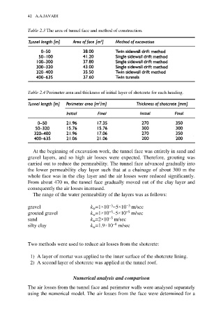
Table 2.3 The area of tunnel face and method of construction.
Table 2.4 Perimeter area and thickness of initial layer of shotcrete for each heading.
At the beginning of excavation work, the tunnel face was entirely in sand and
gravel layers, and so high air losses were expected. Therefore, grouting was
carried out to reduce the permeability. The tunnel face advanced gradually into
the lower permeability clay layer such that at a chainage of about 300 m the
whole face was in the clay layer and the air losses were reduced significantly.
From about 470 m, the tunnel face gradually moved out of the clay layer and
consequently the air losses increased.
The range of the water permeability of the layers was as follows:
−3
−3
gravel k =1×10 −5×10 m/sec
w
−5
−5
grouted gravel k =1×10 –5×10 m/sec
w
−5
sand k =2×10 m/sec
w
−9
silty clay k =1.9×10 m/sec
w
Two methods were used to reduce air losses from the shotcrete:
1) A layer of mortar was applied to the inner surface of the shotcrete lining.
2) A second layer of shotcrete was applied at the tunnel roof.
Numerical analysis and comparison
The air losses from the tunnel face and perimeter walls were analysed separately
using the numerical model. The air losses from the face were determined for a