
Page 64 - Numerical Analysis and Modelling in Geomechanics
P. 64
COMPRESSED AIR TUNNELLING 45
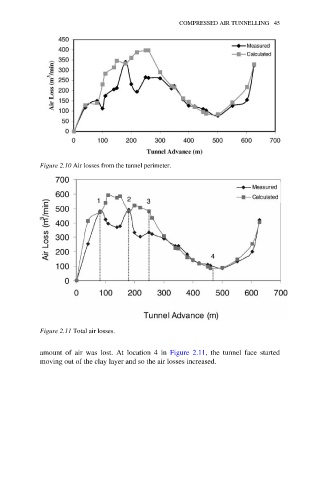
Figure 2.10 Air losses from the tunnel perimeter.
Figure 2.11 Total air losses.
amount of air was lost. At location 4 in Figure 2.11, the tunnel face started
moving out of the clay layer and so the air losses increased.