
Page 60 - Numerical Analysis and Modelling in Geomechanics
P. 60
COMPRESSED AIR TUNNELLING 41
50 m of the tunnel length was constructed using a twin sidewall drift method (see
Figure 2.6a). From 50 m to 320 m, the tunnel was constructed by a single
sidewall drift method (see Figure 2.6b) and from 400 m to 635 m, the tunnel was
converted to twin tunnels (see Figure 2.6c).
Table 2.3 shows the change in the tunnel face area with tunnel advance for
each heading together with the method of construction. Table 2.4 shows the
perimeter area (per unit length of the tunnel) and the thickness of the initial and
final layer of shotcrete.
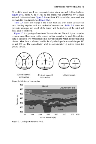
Figure 2.7 is a geological section of the tunnel route. The soil layers comprise
a coarse gravel layer near to the ground surface underlaid by sand. Beneath the
sand is a layer of low permeability silty clay underneath which lies another layer
of sand. Also, there is a lens of sand in the silty clay layer between chainages 300
m and 635 m. The groundwater level is approximately 5 metres below the
ground surface.
Figure 2.6 Method of construction.
Figure 2.7 Geology of the tunnel route.