
Page 246 - Offshore Electrical Engineering Manual
P. 246
Worked Example: Fault Calculation 233
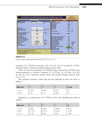
FIGURE 4.5.3
Typical cable sizing spreadsheet (see Web Reference 2).
″
″
reactances X = 0.195 per unit (pu), × X = 0.31 pu, X = 2.2 pu and X = 0.265;
′
d
d
q
d
full-load current, 1550 A and neutral earthing resistor, 10 Ω.
There are four more generators of a different type, each rated at 3.87 MVA and
″
′
having parameters as follows: reactances X = 0.15 pu, X = 0.18 pu, X = 2.05
d
d
d
″
pu and X = 0.15; full-load current, 340 A and neutral earthing resistor, 40 Ω
q
(Fig. 4.5.3).
The generator reactance values (pu) may be tabulated on their own base as
follows:
MVA Unit X d ″ X q ″ X o ″ R n (Ω)
1 × 177 0.195 0.265 0.09 10
1 × 3.87 0.15 0.15 0.045 40
Referring to a common base of 17.7 MVA, 6.6 kV and considering the units in
parallel:
MVA Unit X d ″ X q ″ X o ″ R n
1 × 3.87 0.686 0.686 0.2058 16.25
4 × 3.87 0.1715 0.1715 0.0515 4.06
1 × 17.7 0.195 0.265 0.09 4.06