
Page 245 - Offshore Electrical Engineering Manual
P. 245
232 CHAPTER 5 Conductor Sizing, Load Flow and Fault Calculation
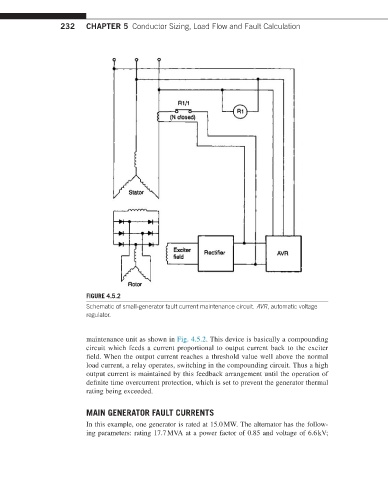
FIGURE 4.5.2
Schematic of small-generator fault current maintenance circuit. AVR, automatic voltage
regulator.
maintenance unit as shown in Fig. 4.5.2. This device is basically a compounding
circuit which feeds a current proportional to output current back to the exciter
field. When the output current reaches a threshold value well above the normal
load current, a relay operates, switching in the compounding circuit. Thus a high
output current is maintained by this feedback arrangement until the operation of
definite time overcurrent protection, which is set to prevent the generator thermal
rating being exceeded.
MAIN GENERATOR FAULT CURRENTS
In this example, one generator is rated at 15.0 MW. The alternator has the follow-
ing parameters: rating 17.7 MVA at a power factor of 0.85 and voltage of 6.6 kV;