
Page 267 - Offshore Electrical Engineering Manual
P. 267
254 CHAPTER 7 Protection and Discrimination
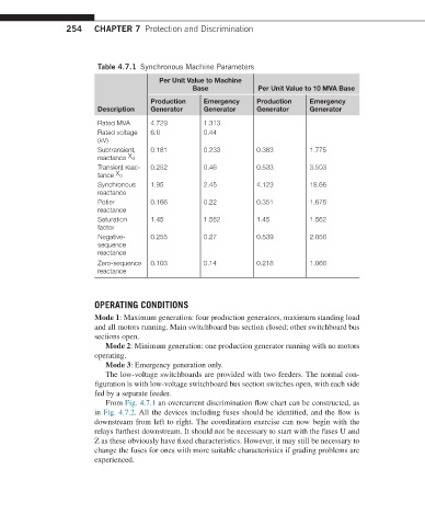
Table 4.7.1 Synchronous Machine Parameters
Per Unit Value to Machine
Base Per Unit Value to 10 MVA Base
Production Emergency Production Emergency
Description Generator Generator Generator Generator
Rated MVA 4.729 1.313
Rated voltage 6.6 0.44
(kV)
0.181 0.233 0.383 1.775
Subtransient ′
X
reactance d
Transient reac- 0.252 0.46 0.533 3.503
′
X
tance d
Synchronous 1.95 2.45 4.123 18.66
reactance
Potier 0.166 0.22 0.351 1.676
reactance
Saturation 1.45 1.562 1.45 1.562
factor
Negative- 0.255 0.27 0.539 2.056
sequence
reactance
Zero-sequence 0.103 0.14 0.218 1.066
reactance
OPERATING CONDITIONS
Mode 1: Maximum generation: four production generators, maximum standing load
and all motors running. Main switchboard bus section closed; other switchboard bus
sections open.
Mode 2: Minimum generation: one production generator running with no motors
operating.
Mode 3: Emergency generation only.
The low-voltage switchboards are provided with two feeders. The normal con-
figuration is with low-voltage switchboard bus section switches open, with each side
fed by a separate feeder.
From Fig. 4.7.1 an overcurrent discrimination flow chart can be constructed, as
in Fig. 4.7.2. All the devices including fuses should be identified, and the flow is
downstream from left to right. The coordination exercise can now begin with the
relays furthest downstream. It should not be necessary to start with the fuses U and
Z as these obviously have fixed characteristics. However, it may still be necessary to
change the fuses for ones with more suitable characteristics if grading problems are
experienced.