
Page 272 - Offshore Electrical Engineering Manual
P. 272
CT Saturation 259
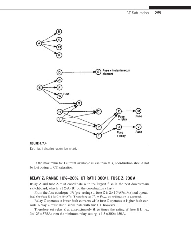
FIGURE 4.7.4
Earth fault discrimination flow chart.
If the maximum fault current available is less than this, coordination should not
be lost owing to CT saturation.
RELAY Z: RANGE 10%–20%, CT RATIO 300/1. FUSE Z: 200 A
Relay Z and fuse Z must coordinate with the largest fuse in the next downstream
switchboard, which is 125 A (B1 on the coordination chart).
2
2
5
2
From the fuse catalogue: I t (pre-arcing) of fuse Z is 2 × 10 A s; I t (total operat-
2
2
ing) for fuse B1 is 9 × 10 A s. Therefore as I t ≫ I t , coordination is assured.
4
2
B1
z
Relay Z operates at lower fault currents while fuse Z operates at higher fault cur-
rents. Relay Z must also discriminate with fuse B1, however.
Therefore set relay Z at approximately three times the rating of fuse B1, i.e.,
3 × 125 = 375 A; then the minimum relay setting is 1.5 × 300 = 450 A.