
Page 83 - Offshore Electrical Engineering Manual
P. 83
70 CHAPTER 5 Generation and Distribution Switchgear and Transformers
(A) Maximum peak asymmetric
I peak = (√2) I sym RMS
System voltage
Fault current
Current (amperes)
Time (ms)
0 5 10 15 20
Instant of fault inception
(B)
Maximum peak asymmetric
I peak = (2√2) I sym RMS
Current (amperes) DC component i Fault current sym
= (√2) I
DC
I sym RMS
System voltage
AC component
i sym
Time (ms)
0 5 10 15 20
Instant of fault inception
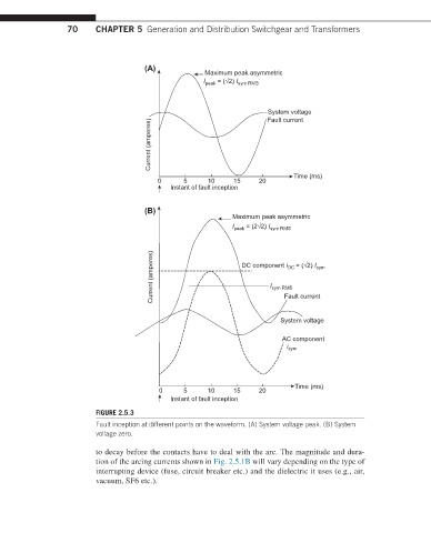
FIGURE 2.5.3
Fault inception at different points on the waveform. (A) System voltage peak. (B) System
voltage zero.
to decay before the contacts have to deal with the arc. The magnitude and dura-
tion of the arcing currents shown in Fig. 2.5.1B will vary depending on the type of
interrupting device (fuse, circuit breaker etc.) and the dielectric it uses (e.g., air,
vacuum, SF6 etc.).