
Page 87 - Offshore Electrical Engineering Manual
P. 87
74 CHAPTER 5 Generation and Distribution Switchgear and Transformers
(A)
(B) Bellows A
End caps Envelope Contact tip Cup End caps
Moving contact
Fixed contact
A A
A
V2O4
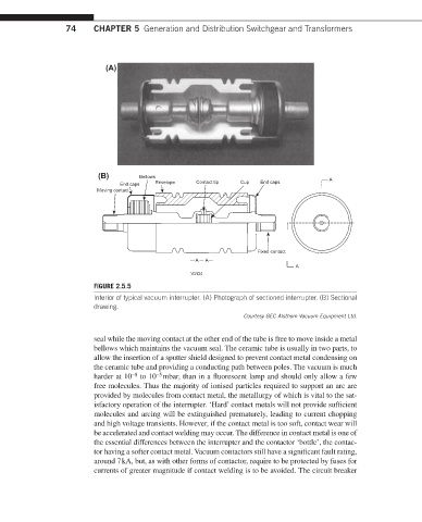
FIGURE 2.5.5
Interior of typical vacuum interrupter. (A) Photograph of sectioned interrupter. (B) Sectional
drawing.
Courtesy GEC Alsthom Vacuum Equipment Ltd.
seal while the moving contact at the other end of the tube is free to move inside a metal
bellows which maintains the vacuum seal. The ceramic tube is usually in two parts, to
allow the insertion of a sputter shield designed to prevent contact metal condensing on
the ceramic tube and providing a conducting path between poles. The vacuum is much
harder at 10 to 10 mbar, than in a fluorescent lamp and should only allow a few
−5
−8
free molecules. Thus the majority of ionised particles required to support an arc are
provided by molecules from contact metal, the metallurgy of which is vital to the sat-
isfactory operation of the interrupter. ‘Hard’ contact metals will not provide sufficient
molecules and arcing will be extinguished prematurely, leading to current chopping
and high voltage transients. However, if the contact metal is too soft, contact wear will
be accelerated and contact welding may occur. The difference in contact metal is one of
the essential differences between the interrupter and the contactor ‘bottle’, the contac-
tor having a softer contact metal. Vacuum contactors still have a significant fault rating,
around 7 kA, but, as with other forms of contactor, require to be protected by fuses for
currents of greater magnitude if contact welding is to be avoided. The circuit breaker