
Page 89 - Offshore Electrical Engineering Manual
P. 89
76 CHAPTER 5 Generation and Distribution Switchgear and Transformers
It is also important that facilities for cabling are as flexible as possible, and that
sufficient space is available for installation of the largest cables without exceeding
bending radii limits. Neutral connection arrangements for outgoing supplies with
neutrals must be provided. Facilities need to be provided for the earthing of cable
armour. If cable entry is at the top, there should be no risk of moisture entering via
the cable entry even if the cables do not have drip loops.
The space requirements for circuit breaker handling trucks must not be forgot-
ten. Functional test facilities should be built in to the switchboard using a test panel
cubicle with bus wiring to each unit to avoid dangerous trailing leads. The test facil-
ity must be interlocked to ensure that live operation of field equipment is impossible
using the test panel. Every unit on the switchboard will require suitable permanent
labeling and interlocking, shuttering and maintenance padlocking facilities. In fact,
all the usual requirements for onshore substations such as safety rubber matting,
earthing facilities and safety testing equipment will be required.
Fault calculations are covered in PART 4 Chapter 6.
Protection relay schemes are covered in PART 4 Chapter 7.
MAIN SWITCHBOARDS 6.6–13.8 KV
The overriding consideration for any main switchboard must be the short circuit
capability of the circuit breakers, because of the fault current capability and proxim-
ity of the installed generation. Generator operational configurations which produce
prospective fault MVAs of more than 1000 should be avoided as downstream equip-
ment and cables would require to be of special nonstandard manufacture with all the
expensive development and testing this would entail, in order to obtain sufficient
rating.
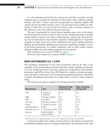
The following are typical examples of switchgear presently available:
Maximum Fault Max. Operating
Manufacturer Type Capacity (kA) Voltage (kV)
ABB Unigear (air 31.5 46
insulated)
ABB ZX (gas insulated) 40 40
ABB Is Limiter a 210 40.5
GE (USA) SecoGear (vacuum) 40 17.5
Powell PowlVac (vacuum) 63 15
Mitsubishi Electric MS-E 40 15
Schneider Electric F400 (vacuum/SF6) 40 40.5
Siemens 8DA10/8DB10 40 42
(vacuum/SF6)
a Recommended for upgrade projects only, where original fault ratings are exceeded.
As discussed earlier in the chapter, a check will have to be made to ensure that the
asymmetrical breaking capacity is adequate, allowing for the decrement in the value