
Page 77 - Oil and Gas Production Handbook An Introduction to Oil and Gas Production
P. 77
For fire detection, coincidence and logic are often used to identify false
alarms. In such schemes, several detectors in the same area are required to
detect a fire condition or gas leakage for automatic reaction. This will include
different detection principles e.g. a real fire, but not welding or lightning
strike.
Action is controlled by a Fire
and Gas system. Like the
ESD system, F&G action is
specified in a cause and
action chart called the Fire
Area Protection Datasheet.
This chart shows all detectors
and fire protection systems in
a fire area and how the
system will operate.
The F&G system often
provides supervisory
functions, either in the F&G
or the Information
Management System (IMS)
to handle such tasks as
maintenance, calibration or
replacement and hot work
permits, e.g. welding. Such
actions may require that one
or more Fire and Gas
detectors or systems are
overridden or bypassed.
Specific work procedures
should be enforced, such as a placing fire guards on duty and make sure all
devices are re-enabled when the work permit expires or work is complete.
6.1.4 Control and safety configuration
Piping and Instrumentation Diagrams (P&ID) show the process. Additional
information is needed for the specification of the Process Control and Safety
Systems.
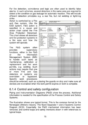
The illustration shows one typical format. This is the common format for the
Norwegian offshore industry: The Njord Separator 1 and 2 Systems Control
Diagram (SCD). Essentially, the P&ID mechanical information has been
removed, and control loops and safety interlocks drawn in with references to
typical loops.
75