
Page 73 - Oil and Gas Production Handbook An Introduction to Oil and Gas Production
P. 73
Loop and Motor Control are defined. This means that the system can be
specified with combinations of typical loops, consisting of one or more input
devices, function blocks and output devices, rather than formal
programming.
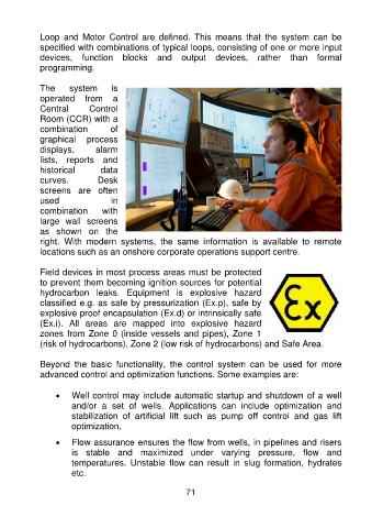
The system is
operated from a
Central Control
Room (CCR) with a
combination of
graphical process
displays, alarm
lists, reports and
historical data
curves. Desk
screens are often
used in
combination with
large wall screens
as shown on the
right. With modern systems, the same information is available to remote
locations such as an onshore corporate operations support centre.
Field devices in most process areas must be protected
to prevent them becoming ignition sources for potential
hydrocarbon leaks. Equipment is explosive hazard
classified e.g. as safe by pressurization (Ex.p), safe by
explosive proof encapsulation (Ex.d) or intrinsically safe
(Ex.i). All areas are mapped into explosive hazard
zones from Zone 0 (inside vessels and pipes), Zone 1
(risk of hydrocarbons), Zone 2 (low risk of hydrocarbons) and Safe Area.
Beyond the basic functionality, the control system can be used for more
advanced control and optimization functions. Some examples are:
• Well control may include automatic startup and shutdown of a well
and/or a set of wells. Applications can include optimization and
stabilization of artificial lift such as pump off control and gas lift
optimization.
• Flow assurance ensures the flow from wells, in pipelines and risers
is stable and maximized under varying pressure, flow and
temperatures. Unstable flow can result in slug formation, hydrates
etc.
71