
Page 233 - Op Amps Design, Applications, and Troubleshooting
P. 233
Low-Pass Filter 215
56kn
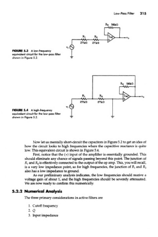
FIGURE 5.3 A low-frequency
equivalent circuit for the low-pass filter
shown in Figure 5.2,
FIGURE 5.4 A high-frequency
equivalent circuit for the low-pass filter
shown in Figure 5.2,
Now let us mentally short-circuit the capacitors in Figure 5.2 to get an idea of
how the circuit looks to high frequencies where the capacitive reactance is quite
low. This equivalent circuit is shown in Figure 5.4.
First, notice that the (+) input of the amplifier is essentially grounded. This
should eliminate any chance of signals passing beyond this point. The junction of
R! and K 2 is effectively connected to the output of die op amp. This, you will recall,
is a very low impedance point, so for high frequencies, the junction of R^ and jR 2
also has a low impedance to ground.
As our preliminary analysis indicates, the low frequencies should receive a
voltage gain of about 1, and the high frequencies should be severely attenuated.
We are now ready to confirm this numerically.
5.2.2 Numerical Analysis
The three primary considerations in active filters are
1. Cutoff frequency
2- Q
3. Input impedance