
Page 237 - Op Amps Design, Applications, and Troubleshooting
P. 237
Low-Pass Filter 219
circuit, the required op amp slew rate (using ±13 volts as the saturation limits) Is
computed as
slew rafe(min) = 3.14 x 1.5 kHz x 26 V = 0.122 V/ys
Finally, the minimum op amp corner frequency may be estimated with Equation
(5.8),
where A OL is the low-frequency, open-loop gain of the op amp and/ c is the filter
cutoff frequency. The corner frequency of the op amp is the one where the open-
loop gain has dropped to 70.7 percent of its low-frequency or DC value. If we
choose a 741 (A OL = 50,000), it must have a corner frequency greater than
Let us consider a 741 op amp for this application. Appendix 1 lists the data for the
741. The minimum bandwidth and slew rate requirements for our application are
exceeded by the 741's ratings. By referring to the graph of open-loop frequency
response in Appendix I, we can estimate the corner frequency of the 741 as about
5 hertz. Again, this exceeds our requirements, so let us choose a 741 for our
design.
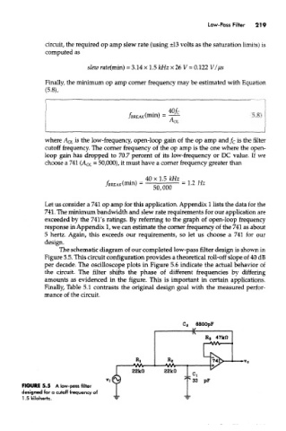
The schematic diagram of our completed low-pass filter design is shown in
Figure 5.5. This circuit configuration provides a theoretical roll-off slope of 40 dB
per decade. The oscilloscope plots in Figure 5.6 indicate the actual behavior of
the circuit. The filter shifts the phase of different frequencies by differing
amounts as evidenced in the figure. This is important in certain applications.
Finally, Table 5.1 contrasts the original design goal with the measured perfor-
mance of the circuit.
FIGURE 5.5 A low-pass filter
designed for a cutoff frequency of
1.5 kilohertz.