
Page 240 - Op Amps Design, Applications, and Troubleshooting
P. 240
222 ACTIVE FILTERS
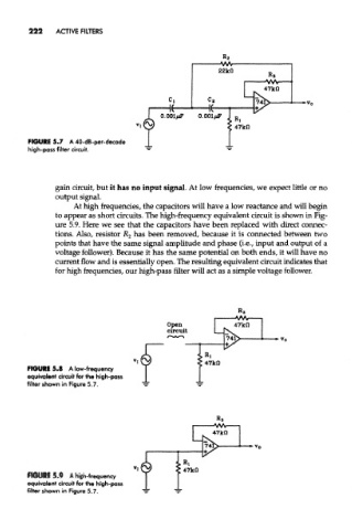
FIGURE 5.7 A 40-dB-per-decade
high-pass filter circuit.
gain circuit, but it has no input signal. At low frequencies, we expect little or no
output signal.
At high frequencies, the capacitors will have a low reactance and wiM begin
to appear as short circuits. The high-frequency equivalent circuit is shown in Fig-
ure 5.9. Here we see that the capacitors have been replaced with direct connec-
tions. Also, resistor R 2 has been removed, because it is connected between two
points that have the same signal amplitude and phase (i.e., input and output of a
voltage follower). Because it has the same potential on both ends, it will have no
current flow and is essentially open. The resulting equivalent circuit indicates that
for high frequencies, our high-pass filter will act as a simple voltage follower.
FIGURE 5.8 A low-frequency
equivalent circuit for the high-pass
filter shown in Figure 5.7.
FIGURE 5.9 A high-frequency
equivalent circuit for the high-pass
filter shown in Figure 5.7.