
Page 242 - Op Amps Design, Applications, and Troubleshooting
P. 242
224 ACTIVE FILTERS
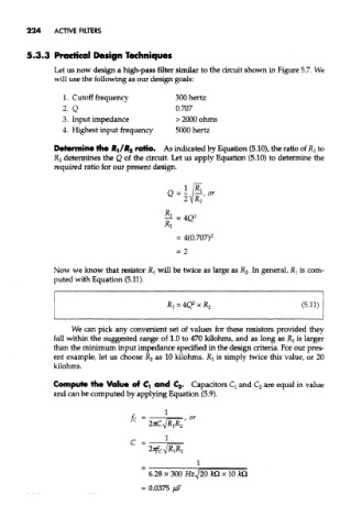
5.3.3 Practical Design Techniques
Let us now design a high-pass filter similar to the circuit shown in Figure 5.7. We
will use the following as our design goals:
1. Cutoff frequency 300 hertz
2. Q 0.707
3. Input impedance > 2000 ohms
4. Highest input frequency 5000 hertz
Determine the R,/R 2 ratio. As indicated by Equation (5.10), the ratio of R } to
R 2 determines the Q of the circuit. Let us apply Equation (5.10) to determine the
required ratio for our present design.
Now we know that resistor Rj will be twice as large as R 2. In general, Rj is com-
puted with Equation (5.11).
We can pick any convenient set of values for these resistors provided they
fall within the suggested range of 1.0 to 470 kilohms, and as long as Rj is larger
than the minimum input impedance specified in the design criteria. For our pres-
ent example, let us choose R 2 as 10 kilohms. RI is simply twice this value, or 20
kilohms.
Compute the Value of Ci and €2* Capacitors Q and C 2 are equal in value
and can be computed by applying Equation (5.9).