
Page 239 - Op Amps Design, Applications, and Troubleshooting
P. 239
High-Pass Filter 221
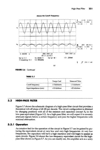
Above the Cutoff Frequency
FIGURE 5.6 Continued
TABLE 5.1
Design Goal Measured Value
Cutoff frequency 1.5 kilohertz 1.3 kilohertz
Input impedance (min) >10 kilohms >22 kilohms
5.3 HIGH-PASS FILTER
Figure 5.7 shows the schematic diagram of a high-pass filter circuit that provides a
theoretical roll-off slope of 40 dB per decade. The circuit configuration is obtained
by changing positions with all of the resistors and capacitors (except R 3) in the
low-pass equivalent (Figure 5.2). As a high-pass filter, we will expect it to severely
attenuate signals below a certain frequency and pass the higher frequencies with
minimal attenuation.
5.3.1 Operation
An intuitive feel for the operation of the circuit in Figure 5.7 can be gained by pic-
turing the equivalent circuit at very low and very high frequencies. At very low
frequencies, the capacitors will have a high reactance and will begin to appear as
open circuits. Figure 5.8 shows the low-frequency equivalent circuit for the high-
pass filter shown in Figure 5.7. As you can readily see, the amplifier acts as a unity