
Page 244 - Op Amps Design, Applications, and Troubleshooting
P. 244
226 ACTIVE FILTERS
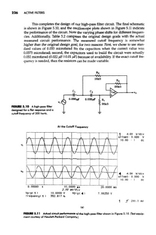
This completes the design of our high-pass filter circuit. The final schematic
is shown in Figure 5.10, and the oscilloscope plots shown in Figure 5.11 indicate
the performance of the circuit. Note the varying phase shifts for different frequen-
cies. Additionally, Table 5.2 compares the original design goals with the actual
measured circuit performance. The measured cutoff frequency is somewhat
higher than the original design goal, for two reasons: First, we chose to use stan-
dard values of 0.033 microfarad for the capacitors when the correct value was
0.0375 microfarad; second, the capacitors used to build the circuit were actually
0,032 microfarad (0.022 /JF110.01 /ip) because of availability. If the exact cutoff fre-
quency is needed, then the resistors can be made variable.
FIGURE 5.10 A high-pass filter
designed for a flat response and a
cutoff frequency of 300 hertz.
At the Cutoff Frequency
FIGURE 5.11 Actual circuit performance of the high-pass filter shown in Figure 5.10. (Test equip-
ment courtesy of Hewlett-Packard Company.)